Organizing Details in Revit

As companies develop their drafting view details inside Revit, the organization of the the details becomes more important. There are many different ways of organizing details inside Revit, but I like this process outlined in this blog article.

Advantages:

  1. It is easy to locate the desired detail within the Revit project file where it is placed.

2. It is easy to locate the desired detail within a detail resource file which contains all of the company’s details.

The key to this process is to organize the details based upon CSI division and to name the details with the division prefix.

Continue reading

Dimension Label in Families

Revit families allow you to create a parameter that controls a dimension, but Revit reacts differently depending on how you select and assign that parameter.

A common work flow process is to create the length parameter(s) in the Family Types dialog box, and then in the graphics window, highlight the desired dimension that is to be controlled by the parameter.  After the dimension is selected, the user selects the desired parameter that is control the dimension.

If the length value has been input already in the parameter value in the Family Types dialog box. Revit will react a couple of different ways when selecting the parameter.

Continue reading

Specifying Formulas for Revit Angles

This article is a quick easy tip for specifying a slope for a line instead of only specifying the angle.  When placing roofs, floors, ceilings, pipes, etc, you have the option for specifying the actual slope, but this option is not available in other situations.

This function is especially helpful with drafting views and similar type situations when the angle of an element needs to be modified.  Since angles cannot be typed/specified when drawing an element, angles are commonly modified after element placement.

Depending on the equation that you enter, you can get a riser/run slope or a percentage slope.  (The angle will still be displayed.)

Continue reading

Revit Slab Depression

It is common to have depressed areas of a concrete floor slab of a building and you want to be able to represent this accurately in a Revit model.  This may be in the middle area of a large floor slab as a containment area or the edge of a floor slab under an overhead door.  Either way, a portion of the floor is lower than the surrounding floor.

Note this article is for a completely depressed area and not one where the edges are the same level and then sloping, as if to a drain.  In those situations, the Shape Editing tools can be used on the floor. 

Continue reading

Project Base Point Clip Gone in Revit 2020.2

Revit 2020.2 release made a change to the Project Base Point that affected many users by removing the clip/unclip capability for it.  Previous releases of Revit had a paper clip symbol that the user could see next to the Project Base Point symbol as shown below.

While this clip feature is no longer part of Revit as of the 2020.2 (it is still in 2020.1), the user still has the capability to move the project.

Continue reading

Modeling in Revit With Point Clouds

Points clouds are becoming more commonly used as a resource for creating a Revit model.  In my Revit model creation from point clouds, I use a few techniques that I am sharing in this article to help ease the process for you.  While I am sure some others do things a bit different, I have found that these work well for me.  There are some tools on the market that assist in getting a Revit model from a point cloud, but many people do not have the financial resources for them or rarely use point clouds.  Therefore, this article is geared to those not having any additional tools.

This article does not address how to create a point cloud or manipulating it outside of Revit.  It only addresses using the point cloud for creating a Revit model.

Continue reading

Revit eTransmit

When sending a Revit project file to another person or company, it is nice to be able to send all of the associated files with the project file.  Revit has incorporated this command, thus enabling us to package up the required files to be sent together.  This is an easily overlooked command and many people are not aware of it.  AutoCAD has had this command for many versions.

Files included in the transmittal:

  • Linked Revit model
  • CAD links
  • DWF Markups
  • Decal Images
  • External Keynote File

Go to the Add-Ins tab of the menu system at the top.

Select the Transmit a model icon from the eTransmit panel.


Notes:

  •  Save all models prior to running the command.
  • Close all models.
  • Additional supporting documents can be added to the transmittal
  • Revit files prior to 2012 need to be upgraded to the 2012 version


Easy Revit Cabinet Crown Molding

Placing crown molding at the top of cabinetry is very common in residential design and can be easy to do in Revit.  Ideally, I would like to use a sweep with a crown molding profile, but Revit utilizes sweeps only for walls when not in the family editor.  The trick to making this an easy process for the user is to create a specialty wall that has the desired sweep profile built into it.  This allows you draw the “wall” to follow the front edge of the cabinetry at the desired elevation for the crown molding.

The following image shows the resultant crown molding.

Continue reading

Revit 2020 Family Offset Parameter

With each release of software, there seems to be little things that change, but are either not documented as a change or the documentation on being a change is buried and difficult to locate.  In Revit 2020, there are some changes in the built-in parameters for families when they are placed in a project file.  These changes can come into play when using automation, such as Dynamo.  While they may or may not have much impact on your particular usage of Revit, it is important information of which to be aware.

Continue reading

Opening with Varying Widths Throughout Revit Wall

It is common to have openings in walls that are not of a consistent width all the way through the wall.  An example of this is when a door is recessed into a brick wall and the brick opening is wider than the stud/masonry wall opening or the door.  The following illustration shows a door opening in a stud and brick wall with the brick opening wider to allow brickmould casing around the door.

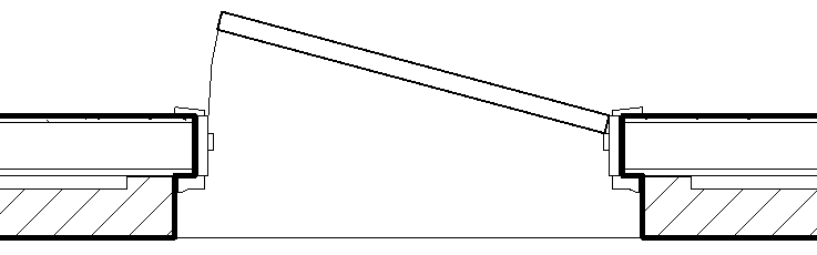
Revit doors and windows, by default, have an opening that goes straight through the wall with a completely rectangular opening.  If you just use the default Door.rft or Window.rft with the default opening to create your doors and window families, you will not see the above jogged offset opening.

The secret to getting the walls to cut as you desire is to NOT use the Opening Cut that is in the family template, but use Voids instead.

Continue reading

Space Name Update to Room Name

Within Revit, it is standard procedure for architects to use “Rooms” and engineers to use “Spaces” to delineate areas of the building.  This is due to how Revit utilizes each of these 2 categories of items, so each have their place.  An issue with this procedure is that Spaces and Rooms for the same area should have the same name, but this does not happen automatically.  This can cause problems with consistency between the architect’s plans and the engineer’s plans.

Since the 2017 version, Revit has given us a tool to help keep Room names and Space names consistent.  Prior to 2017, we had to rely on either naming the Spaces manually or utilizing one of the 3rd party tools on the market.  With this command, we can update all of the Spaces in the entire model to be the same as a Room that is in the same bounded area (if there is a Room element there.)  Autodesk slipped this command into the menu system and I don’t remember them promoting it, but it is a fantastic tool for engineers!  It can save hours of work trying to get Room and Space Names consistent.

Continue reading

Electrical Panel Feed Thru Lugs in Revit 2020

Revit 2020 has a new feature that will please Electrical designers.  Feed through lugs are now incorporated into Revit for your electrical distribution system.  Previously, electrical users had to utilize workarounds to represent this situation in their designs, so this will improve the documentation process and help with the electrical design.

As part of this new feature, Revit has added a new panel schedule template, which is called “Feed Through Lugs Panel“.  This panel is available in the Electrical-Default.rte and the Systems-Default.rte templates.  This panel template is accessible via the Manage tab -> Settings panel -> Panel Schedule Templates.


The process to actual set up the electrical panels to utilize the above Panel Schedule is shown below. Continue reading