Many pieces of equipment in a building have clearance zones that are required around the equipment for a variety of reasons. It may be a drinking fountain that requires ADA clearance, an electrical panel that requires code clearance in front it, or mechanical equipment that requires air movement or access clearance around it. For whatever the reason, it is good to build that clearance zone into the Revit family so that it be used for interference detection through Revit or Navisworks.
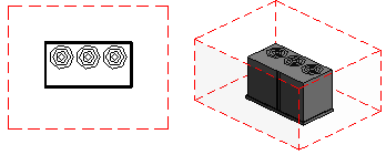
Many families provided by manufacturers that could utilize clearance zones are not created with them. This may partly be due to Autodesk Seek not having it as part of the Seek standards, since many manufacturers develop content to place on the Seek website at seek.autodesk.com. However, the Australia and New Zealand Revit Standards (ANZRS) includes the Clearance Zones as part of the standards when needed. I would like to see Revit family creators utilize Clearance Zones as a standard practice. The following illustration shows what the Clearance Zone would look like around an air condenser:

The following sections describe my recommendations for adding Clearance Zones into Revit families.
Object Style Subcategory
A Subcategory named Clearance Zones needs to be added to the object style Category for the family. By having a Subcategory specifically for clearance zones, then the user can manipulate the visibility characteristics of the clearance zone in a project view. These clearance zones are also assigned an extrusion which will allow for clash detection for items infringing on the zones.
The following types of family categories may commonly get this Subcategory:
- Electrical Equipment
- Mechanical Equipment
- Plumbing Fixtures
- Generic Models
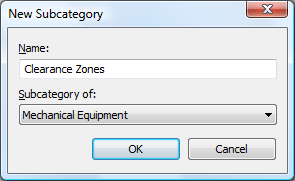
To create the new subcategory, go to the Manage tab and select the Objects function from the Settings panel. In the Object Styles dialog box, pick the New button under Modify Subcategories in the lower right corner. In the New Subcategory dialog box, type the name “Clearance Zones” and pick the OK button.

In the Object Styles dialog box, change the Line Color of the new Clearance Zones to Red and the Line Pattern to Hidden. (Note that the project templates from Revit have a line pattern named Hidden 1/16 which may work better for you.) The new Clearance Zones material created in the next section can also be added as the Material to the new subcategory.

Clearance Zones Material
A new material named Clearance Zones should also be added to the family. When an extrusion is created in the family, it can be assigned this material so that the appearance and visibility of the material can be controlled by the user in the project file if desired. Since the extrusion will be used for clash detection, it can have a material which is specifically for the clearance zones.
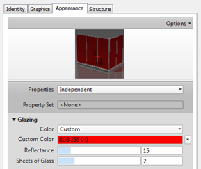
It is recommended that the new Clearance Zones material be assigned a semi-transparent property so that 3D views will show the clearance zone extrusion, but also allow the user to see other objects around it. If the user duplicates the Glass material as the basis for the new material, the user only needs to give it some color to make it easy to see.

Highlight the Clearance Zones material, go the Appearance tab and change the color in the Glazing section.

Part 2 explains creating the reference planes, parameters, and the actual mass for the Clearance Zone. It also lists resources for Revit family standards.

Pingback: Clearance Zones in Revit Families – Part 2 « Applying Technology to Architecture
Pingback: Revit Architecture India » Designing Revit Content – What is Interference?
Hi Doug.
I think this is a good idea to partially implement for NZ and Aus industries, since it can be done without incurring much of a family overhead, and for sure it is widely used internationally. I would hope that the native Revit Interference Check, would have no issues with the geometry aspects, however, typically, a range of methods are used for these sorts of issues such as filled regions, invisible lines and void cages as well as model or detail lines.
Revit interference checking would not see filled regions for a start ?
I can think of a number of examples where the family having built in clearance edges, could help – for instance, AS/NZS 3000 Wiring Rules – where electrical fittings such as power outlets, are placement restricted with respect to wet zones 1,2,3 etc, or for accessible bathroom or toilet facilities where fixtures and fittings have positional requirements for code compliance – having such a family with the clearance parameter could help with instant positioning in terms of minimum distances (for example).
Thanks so much! was looking everywhere for this, very helpful. Thanks!