
I recently had someone ask me how to use Revit to connect an electrical panel to another electrical panel via lugs. This situation occurs at times in building construction where an electrical sub-panel is wired into another panel via the lugs in the first panel and does not actually use a breaker in the first panel. This is not normal practice, but does occur. (Note that this is different than having an electrical sub-panel that has main lugs and does not have a main breaker which actually DOES use a breaker in the panel that feeds the sub-panel.)
For our situation described here, Panel A has a 200 Amp main breaker that controls just the circuit breakers that are seen in Panel A. Panel B also has a 200 Amp main breaker, but is wired into Panel A at the main lug prior to the Panel A main circuit breaker. In this case, Panel B needs to show in Revit as fed from Panel A but does not utilize a breaker in Panel A. By default, Revit will create a breaker on Panel A to control Panel B. We do not want that to happen in this situation.
There is a way around having Revit showing a breaker in Panel A for sub-Panel B, and that is to assign Panel B to circuits that are not shown on Panel A. Since most panels have a maximum of 42 circuits, you can create a panel with 48 circuits and temporarily use this panel schedule for Panel A while assigning Panel B to the panel. After assigning Panel B to a high breaker number on Panel A, you can change Panel A to use a panel schedule with the correct number of breakers.
The following steps describe this process.
Create a Panel Schedule Template for Panels with 48 Circuits.
- Go to Manage tab and choose the Manage Template option from the dropdown list of the Panel Schedule Templates button on the Settings panel.
- Highlight the Branch Panel (Default) template and pick the Duplicate button at the bottom of the Manage Panel Schedule Templates dialog box.
- In the Duplicate Panel Schedule Template dialog box, name the new template Branch Panel – 48 Circuits. Pick the OK button.

- Highlight the new Branch Panel 48 Circuits template and pick the Edit button at the bottom of the Manage Panel Schedule Templates dialog box. The panel layout now appears.
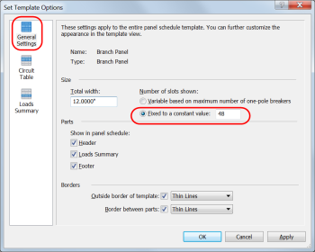
- Select the Set Template Options button on the left end of the Template panel of the ribbon.
- In the Set Template Options dialog box, highlight General Settings in the upper left portion. Select the “Fixed to a constant value:” option in the middle of the dialog box and change the quantity from 42 to 48. Pick the OK button.
- Pick the green checkmark Finish Template button from the Template Editor panel on the ribbon to finish editing the new template.
- This now provides a panel schedule for panels that contains 48 circuits.

Place Electrical Panels
- Place 2 electrical panels.
- Assign both panels to a distribution system. (They must both be on the same distribution system.)
- This can be done via the Properties palette or the Options Bar when the panel is selected.
- Highlight the first panel and name it “A” in the Panel Name parameter of the Properties palette.
- With Panel A still highlighted, go to the Electrical – Circuiting section of the Properties palette and change the Max #1 Pole Breakers parameter to 48.
- This must be done to allow Panel B to be moved to the desired circuit in a later step.
- Highlight the second panel and name it “B” in the Panel Name parameter of the Properties palette.
- Your organization will undoubtedly have other naming conventions for electrical panels.

Assign Panel Schedule and Breakers
- Highlight Panel B. On the Create Systems panel of the ribbon, select the Power button.
- On the System Tools panel of the ribbon, go to the Panel option and pick “A” from the dropdown list.
- Highlight Panel A. Select the “Choose a Template” option from the dropdown list of the Create Panel Schedules button on the Electrical panel.
- In the Change Template dialog box, select the Branch Panel – 48 Circuits option. Pick the OK button. The panel schedule for Panel A is now displayed in the graphics window.
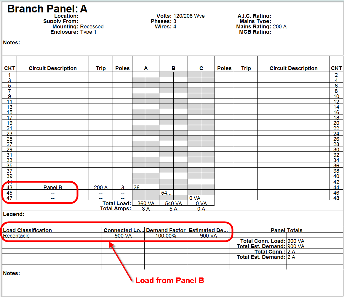
- Highlight Panel B in the panel schedule. Go to the Circuits panel and select the Move Down button. Repeat picking this button to move it down to the bottom of the electrical panel so that it uses spaces 43,45,47. (Use the Move Across button as well if you desire the panel to use spaces 44,46,48.)
- Pick the Change Template button on the ribbon.
- In the Change Template dialog box, select the Branch Panel (Default) option.
- You will get a couple of warning messages. Pick Yes for first message about proceeding, and then ignore the second message.
- This makes Panel A display only 42 circuits, so Panel B will not display on the panel schedule.
Notes:
- The load calculations for Panel B will appear in the load calculations for Panel A and will add both loads together for totals shown in Panel A.
- If Panel B requires 3 spaces, you will not be able to move it down the panel after other circuits have been added to Panel A.
- The above procedure does not create a complete electrical system, but just illustrates portion needed for the point of this post.
- A Main Circuit Breaker (MCB) panel has a main breaker contained in the panel that can be switched off to cut power to the circuits in the panel. A Main Lug Only (MCO) panel has main lugs which is fed from another panel (or disconnect) which actually contains the breaker used to cut power to the circuits in the MCO panel. An MCO panel does not have a breaker in the panel that will cut the power to the circuits.

PERFECT! This is a perfect solution when using double section panels. Thanks.