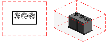
My previous article discussed the importance of creating Clearance Zones inside Revit familes for equipment and items that need clearances for ADA, safety, air movement, or other reasons. While that article also discussed the behind the scenes set up to get Clearance Zones into a Revit family, this article finishes the process of creating the actual Clearance Zone.
The following sections describe the process of creating the actual Clearance Zones.
Creating Clearance Zone Constraints
Reference Planes are an important part of creating constraints for almost everything in a family, so this is where the clearance zone starts. Create reference planes on each side of the item where the clearance zone is required. (If the clearance zone is only required on the front side of the equipment, then you only need a new reference plane on the front. The back and side reference planes for the equipment can be used as boundaries for the clearance zone.) If clearance zone space needs to include area above or below the unit, then reference planes need created in those areas as well. The key point to keep in mind is that you need reference planes to form a complete 3D boundary around the entire equipment and necessary clearance zones.
Make sure that you name each of the reference planes during the process so that everyone will know the purpose of each of them. (This should always be done for all reference planes in a family.) Give them names such as “Clearance Zone Front Face” or “Clearance Zone Left Face”, as an example.
The Is Reference property for each reference plane is very important, and needs to be adjusted appropriately as required for each situation. A previous blog article entitled “Revit Family Reference Planes IsReference Property” addressed this property and should be referenced in determining which option to utilize for your situation. In most situations, you will either use the “Not a Reference” or “Weak Reference” options, depending on whether you want to snap to this reference plane.
Establish Clearance Zone Distances
After the reference planes have been created, dimensions need to be used to establish each of the clearance zone distances from the equipment. If the distance from the equipment to the edge of the clearance zone is always a fixed distance, then a standard dimension can be placed. Make sure that the dimension is locked so that the reference plane can not be moved.
Sometimes the clearance zone distance needs to change, such as different distances based upon the family type requirements. (Different sizes (types) of a piece of equipment may require differenct clearances.) When the clearance distances need to vary, then a Length parameter needs to be created. After placing a dimsension for the clearance, highlight the dimension and select the <Add Parameter…> option from the Label parameter on the Options Bar. In the Parameter Properties dialog box, select the Family Parameter option and make it a Type parameter. Provide a meaningful name which will be very obvious for any future users of the family, and group the parameter under Constraints.
 Create a Length parameter for each clearance edge that requires it. This may be for only one side or as many as six if each side, top, and bottom require different distances based upon the family type.
Creating the Extrusion
After the constraints are in place, use the Extrusion command from the Home tab to create an extrusion that will encompass the entire piece of equipment and the entire clearance zone space. Make sure that you lock each edge of the extrusion to the reference planes that surround the clearance zone. Don’t forget to lock the top and bottom of the extrusion to the appropriate reference planes as well.
If the clearance zone is only in front of the equipment (such as ADA access for a drinking fountain or access to an electrical panel), then it may be best to just create the extrusion in only the required area and not include the equipment itself.
After the extrusion has been created, select the extrusion and change the Material property to the previously created “Clearance Zone”. Change the Subcategory property to “Clearance Zone” that was also previously created in the Part 1 article.

After the extrusion is created and assigned to the Clearance Zones properties, the end user will be able to turn the Clearance Zones subcategory on/off, change its color or linetype, or control other visibility aspects as desired. It is likely that the Clearance Zones subcategory will be turned off most of the time in the project file.

Resources
The following are links to resources for Revit family standards:
