
An important aspect of using Revit MEP is the ability to place pipes for various piping needs of a building project. When placing pipes, the user specifies the pipe size and elevation, but those have some caveats which may not be readily apparent or what the user assumes. There are pipe settings and parameters for diameter, nominal diameter, outside diameter, inside diameter, invert elevation, and justifications, which all interact with each other to determine the actual location of a pipe.
It can be a bit daunting understanding how the various pipe size parameters interact with elevation distances and dimensions. Hopefully, this article will help make it less daunting.
Let’s take a look at the various aspects of pipe sizing.
First off, it is important to understand how the sizes of pipes are specified.
Go to the Manage tab, and the Settings panel, and select the Mechanical Settings dropdown option from the MEP Settings command. In the Mechanical Settings dialog box, expand the Pipe Settings group and select Segments and Sizes. The following illustration shows the settings for Polyvinyl Chloride – Rigid – Schedule 80 pipe:

In the above illustration, there are 3 important sizes of which you need to be aware and will be referenced throughout this article.
- Nominal = this is the general pipe size diameter that is referenced by users, engineers, contractors, etc.
- ID = this is the actual inside diameter of the pipe.
- OD = this is the actual outside diameter of the pipe.
- For example, the PVC Schedule 80 pipe that is in the illustration has a 4″ Nominal size, but has an inside dimension (ID) of 3-13/16″ and an outside diameter (OD) of 4-1/2″.
Different pipe types (segments) will generally have different ID and OD sizes since the pipe material is different.
Now, let’s take a look at elevation dimensions.
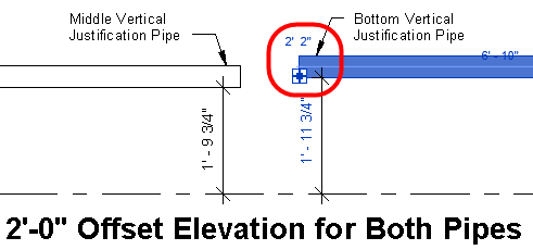
The following illustration shows an elevation view of two 4″ PVC pipes. The pipe on the left was placed with specifying a 2′-0″ offset elevation using a Vertical Justification setting of Middle. The pipe on the right was placed with specifying a 2′-0″ offset elevation using a Vertical Justification setting of Bottom. (The Bottom justification is often used when desiring to specify an invert elevation of the pipe or to clear obstructions.) The dimensions show the dimension supposedly to the outside face of the bottom of each pipe.

In the illustration above, notice that the dimension on the left is equal to 2′-0′ (the offset) minus 2-1/4″, which is half of the outside diameter (OD) of the pipe. This makes sense since the 2′-0″ was specified to the middle of the pipe and we want to find the outside face of the pipe. The dimension on the right is equal to 2′-0″ minus 1/4″. This seems confusing since the wall of the pipe is actually 11/32″ (4-1/2″ OD minus 3-13/16″ ID, then divided by 2).
The method that Revit uses to calculate the above dimensions are:
- For Middle justification = Offset elevation (2′-0″) minus half of the pipe OD dimension (2-1/4″).
- For Bottom justification = Offset elevation of the pipe (2′-0″) plus half of the pipe Nominal dimension (2″) minus half of the pipe OD dimension (2-1/4″). (yes, it seems strange to me)
- For Top justification = Offset elevation of the pipe (2′-0″) plus half of the pipe Nominal dimension (2″) plus half of the pipe OD dimension (2-1/4″). (This option was not shown above.)
Now, let’s move on to the elevations shown in Properties of the pipes.
When selecting the Middle justified pipe on the left, note that the Offset parameter says 2′-0″. Also, note that the Invert Elevation parameter says 1′-10 3/32″. This is accurate based upon the center of the pipe being at 2′-0″ since 2′-0″ minus half of the pipe ID (3-13/32″ divided by two = 1-29/32″) equals 1′-10 3/32″. Note that the Diameter parameter in the pipe Properties specifies the Nominal pipe diameter and not actual diameter. The Invert Elevation is NOT the same as the dimension that we placed earlier and shown in the above illustration.

When selecting the Bottom justified pipe on the right, note that the Offset parameter says 2′-2″ even though it was placed with an Offset value of 2′-0″. Revit will always specify this Offset value as the center of the diameter of the pipe. Since we specified an Offset elevation of 2′-0″ when we placed the pipe using Bottom justification, Revit takes that 2′-0″ and adds half of the Nominal size (2″ = 4″ divided by 2) of the pipe to get the Offset parameter distance. It is important to note that the Invert Elevation parameter says 2′-0 3/32“. This is accurate based upon the center of the pipe being at 2′-2″ since 2′-2″ minus half of the pipe ID (3-13/32″ divided by two = 1-29/32″) equals 2′-0 3/32″.

When pipe is selected and highlighted in a view, the pipe segment will display the Offset elevation at the end of the pipe. This will be either the Start Offset or End Offset elevation shown in the Properties for the pipe segment. Note that the displayed elevation is based upon the centerline of the pipe and does not display the bottom elevation even when the Bottom justification is specified. This is seen in the second illustration where the pipe connector is shown at the bottom of the pipe, but the elevation is given for the centerline of the pipe. The offset elevation shown is NOT to the pipe connector.

Finally, let look at what the Pipe Elevation tags show.
When placing the default OOTB Invert Elevation Pipe Tag.rfa annotation tag, the tag will read the Invert Elevation parameter for the pipe, which was just discussed above. The following illustration shows a tag placed for each of the two pipes:

Summary
- An important thing to remember when working with pipes is that pipe sizes are referenced by the Nominal size versus actual size.
- When placing pipe so that it clears beams, etc, you will need to factor in actual OD size and not just the Nominal size.
- The Invert Elevation will be accurate based upon the selected pipe size and the pipe centerline elevation.
- Dimensions that are placed may or not be accurate for what you desire depending upon how the pipe was placed.
- When highlighting a pipe segment the elevation shown in the view at the end of the pipe segment will be reading the Offset parameter.

Pingback: Bottom of Pipe Tag for Revit 2015 | A Word on BIM
Pingback: Bottom of Pipe Tag for Revit 2015 - Revit news